
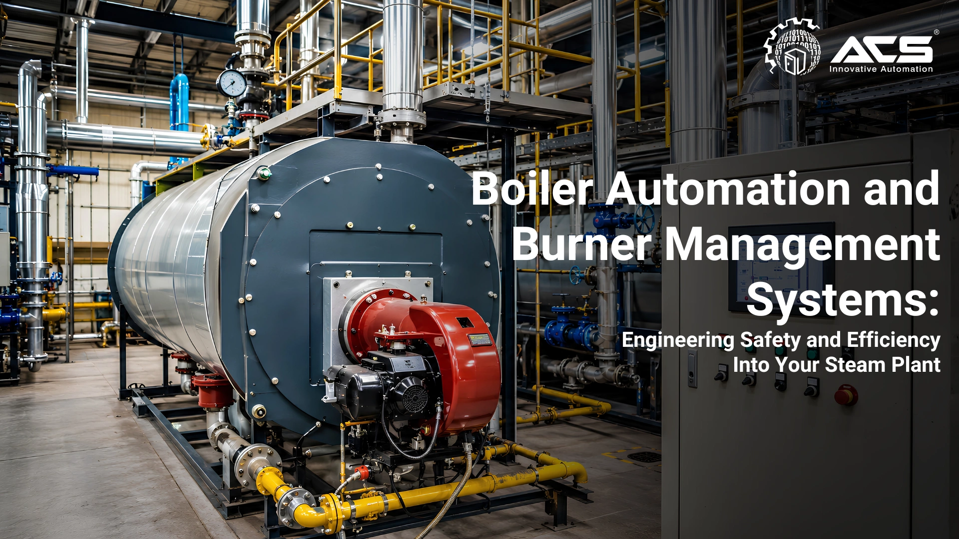
Boiler Automation and Burner Management Systems: Engineering Safety and Efficiency Into Your Steam Plant
When it comes to boiler automation system, why Boiler Automation Is a Different Engineering Challenge
The industrial boiler sits at the intersection of three engineering disciplines: combustion engineering, thermal engineering, and control systems. Getting any one of these wrong creates consequences that range from efficiency loss to catastrophic failure.
Boiler automation is not simply 'automating a process.' It must coordinate combustion, steam pressure control, feedwater balance, permissives, alarms, and independent safety functions. The control and safety architecture should be selected through risk assessment and the applicable code requirements.
At ACS Engitech, boiler automation projects are among our most technically demanding. This blog explains what a properly engineered boiler automation system looks like , technically and practically.
The Burner Management System (BMS): The Safety Layer
The Burner Management System is the safety critical control layer that governs the startup, operation, and safe shutdown of a burner. It is not simply a sequence controller. It is a safety system governed by international standards:
- ISO 135772:2023: Safety requirements for combustion and fuel handling systems used with industrial furnaces and associated processing equipment
- NFPA 85: Boiler and Combustion Systems Hazards Code , applicable to defined boiler and combustion system categories, subject to jurisdiction and equipment scope
- Applicable Indian boiler regulations, local authority requirements, OEM instructions, and the plant's approved causeandeffect philosophy
The BMS Sequence: Every Startup, Every Time
A correctly engineered BMS enforces an approved startup and shutdown sequence with controlled reset and bypass management. Exact timings, purge volumes, valve arrangements, and proof requirements must follow the applicable code, burner OEM, boiler design, and approved causeandeffect matrix. A typical sequence includes:
1. Prepurge: The furnace and connected gas paths are purged at a verified airflow for the required duration or purge volume before ignition. The permissive must prove the required fan and damper conditions; generic purge values should not be copied between boiler designs.
2. Pilot ignition: Where a pilot is used, it is ignited within a defined trialforignition period and proved by an approved flame detection system. The permitted trial time is application specific.
3. Main fuel valve opening: Only after pilot flame is confirmed does the BMS permit the main fuel valve to open. If pilot flame is not detected within the trial period, the BMS initiates a lockout, a safe state requiring manual reset.
4. Main flame proving: The main flame is proved and continuously supervised. A lossofflame condition initiates the certified safety response, including fuel isolation and the required shutdown or purge sequence.
5. Postpurge: On normal shutdown or trip, a postpurge cycle clears residual fuel from the furnace.
Critical Safety Interlocks in Boiler Automation
Beyond the BMS sequence, a properly automated boiler has a matrix of hardwired and PLCbased safety interlocks:
| Interlock | Trip Condition and Action |
|---|---|
| LowLow Water Level | Drum level below minimum → Immediate burner trip and fuel valve close. Prevents catastrophic dryfire. |
| High Steam Pressure | Steam pressure above maximum → Burner modulation to minimum, then trip if not resolved. Protects against overpressure event. |
| Flame Failure | No flame detected during operation → Fuel is isolated within the validated safety response time. Prevents unburnt fuel accumulation. |
| Combustion Air Pressure Low | Induced/forced draft fan flow below minimum → Fuel trip. Prevents incomplete combustion. |
| Fuel Gas/Oil Pressure HighHigh | Abnormal fuel pressure → Fuel valve close. Prevents overfiring. |
| Fuel Gas/Oil Pressure LowLow | Fuel pressure drop → Fuel valve close. Prevents lean burn and loss of flame. |
| Critical requirement: Safety functions must remain effective after a foreseeable controlsystem fault. Depending on the risk assessment, this may require hardwired circuits, certified safety relays, a failsafe PLC architecture, or a combination of independent protection layers. | For SILrated applications, Siemens SIMATIC Safety FPLCs (FailSafe PLCs) are used to execute the BMS logic in a certified safety environment. |
Steam Pressure and Drum Level Control: The Process Automation Layer
Steam Pressure Control , SingleElement
The most basic steam pressure control uses a single PID loop: steam header pressure measured by a pressure transmitter drives burner firing rate (fuel valve modulation or burner incremental control). As steam demand increases and pressure falls, the controller opens the fuel valve to increase firing. As demand falls, firing reduces.
Drum Level Control, Three Element
Drum level control in a boiler is one of the most critical and technically interesting control problems in process automation. The complication: drum level responds counterintuitively to changes in steam demand, a phenomenon called 'shrink and swell.'
Shrink and Swell: When steam demand suddenly increases, boiler pressure momentarily drops. This causes dissolved gases in the drum water to flash, temporarily raising drum level , even though actual water inventory is falling.
A simple singleelement (level only) controller will REDUCE feedwater flow when level rises due to swell, making the actual lowwater situation worse.
The correct solution, three element drum level control, uses three measurement inputs:
- Steam flow measurement (process demand signal)
- Drum level measurement (primary controlled variable)
- Feedwater flow measurement (manipulated variable feedback)
The control strategy: feedwater flow is set to match steam flow as a feedforward signal, with drum level providing a trim correction. This eliminates shrink/swell effects and provides stable drum level across all load conditions.
Combustion Efficiency: O2 Trim Control
Efficient combustion requires a controlled agrofuel ratio. Excess air increases stack losses, while insufficient air can increase carbon monoxide, smoke, instability, and combustion risk.
O2 trim control uses a suitable flue gas oxygen analyzer to measure residual oxygen and trim the combustion air command. The target oxygen level is fuel, burner, load, and site-specific and must be established during combustion tuning.
Sitespecific
Efficiency benefit depends on baseline tuning, load profile, fuel, and excessair condition
Verified purge
Airflow and purge volume or duration must be proven for the specific system
Validated
Safety response time must satisfy the applicable code and certified safety design
Stable control
Threeelement control improves loadresponse performance when correctly commissioned
The ACS Engitech Boiler Automation Package
A complete boiler automation system from ACS Engitech includes:
- Siemens S71500 or S71200 PLC (with FCPU for SIL rated BMS applications)
- Siemens SIMATIC HMI with colour P&ID mimic of the boiler and burner system
- Hardwired BMS logic with certified safety relays for critical trips
- Three element drum level control loop with auto manual transfer
- Steam pressure PID with load tracking and cascade options
- O2 trim control integration (if client provides flue gas analyzer)
- Comprehensive alarm management: priority rated alarms with timestamped event log
- Remote monitoring capability via Siemens WinCC SCADA and secure VPN
Conclusion: Boiler Safety Is Not Optional, And Neither Is Engineering Rigour
A boiler automation system that is designed to standards, built with appropriate hardware, and commissioned by engineers who understand combustion and control is not just a regulatory checkbox , it is the foundation of safe, efficient, and reliable steam generation.
The cost of an under engineered BMS , in terms of fuel waste, maintenance burden, and catastrophic failure risk , far exceeds the cost of doing it correctly the first time.
Suggested social hashtags: #BoilerAutomation #BurnerManagement #BMS #NFPA85 #Siemens #ProcessAutomation #SteamPlant #ACSEngitech #IndustrialSafety
About ACS Engitech Pvt. Ltd.
Since 2009, ACS Engitech has delivered automation solutions across manufacturing sectors. As a Siemens Channel Partner, we provide comprehensive automation systems including PLC panels, SCADA implementation, and remote monitoring solutions. Our 6000 sq. ft. manufacturing facility in Ahmedabad serves clients across India with ISO 9001-certified control panel solutions.
Take Action Today
Ready to optimize your facility? Connect with us to discuss how automation can improve your operations and address critical demands.
Connect With Us