
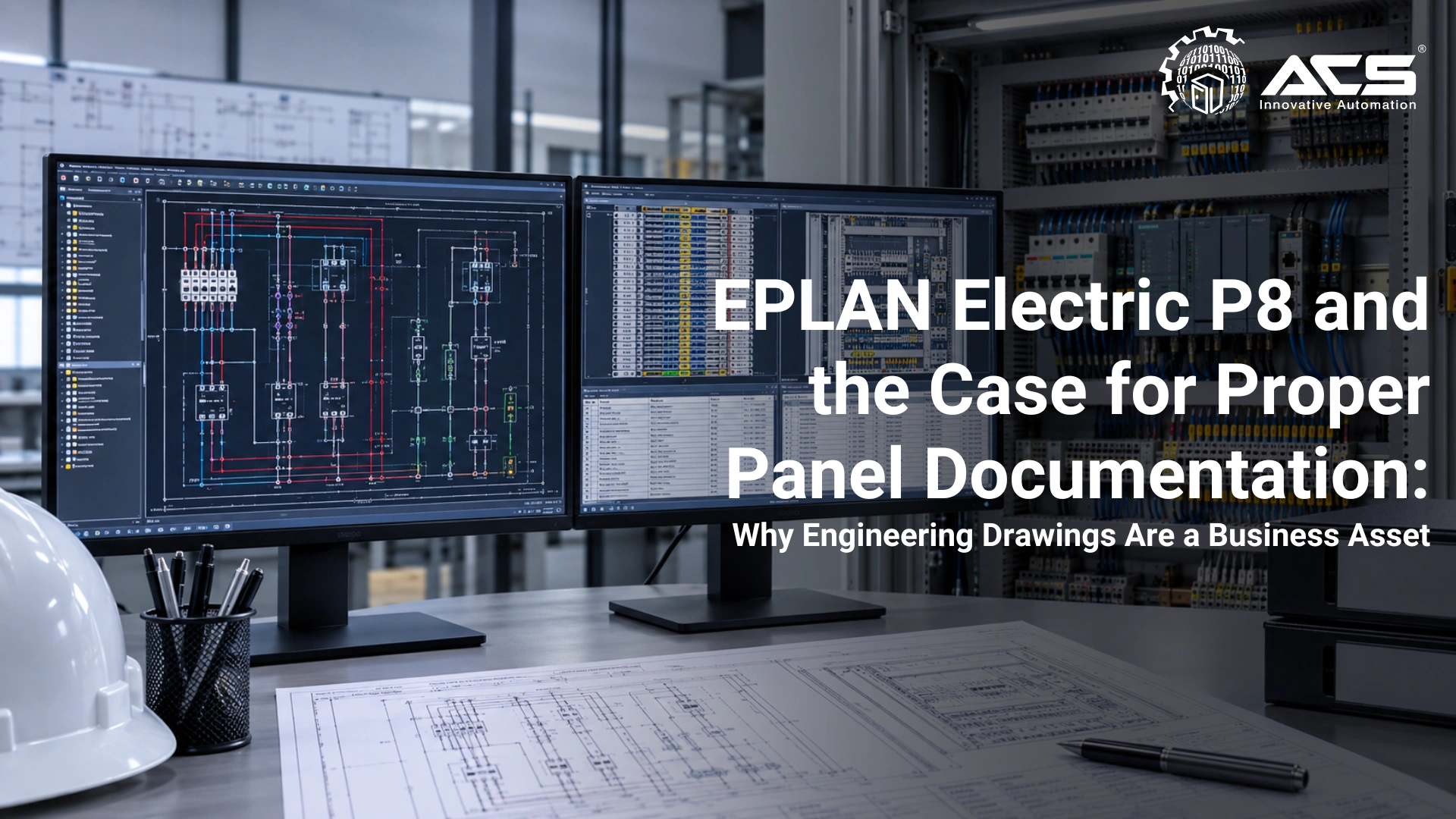
EPLAN Electric P8 and the Case for Proper Panel Documentation: Why Engineering Drawings Are a Business Asset
When it comes to electrical panel design, what EPLAN Electric P8 Is and Why It Matters
EPLAN Electric P8 is a Computer Aided Engineering (CAE) software platform for electrical engineering. Unlike AutoCAD (a general-purpose drafting tool), EPLAN is a rule based engineering environment where every element of a schematic has a database identity , components, terminals, cables, wires, and devices are all data objects, not just drawn symbols.
The implications of this distinction are significant:
- A component placed in the schematic automatically generates a BOM (Bill of Materials) entry
- A terminal drawn in the schematic automatically populates the terminal strip diagram
- A cable drawn between two terminals generates a cable list entry
- Cross-references between schematic pages are computed automatically , not manually drawn
- Changes to component data in one location propagate throughout all derived documents
The EPLAN Documentation Package: What a Complete Set Looks Like
| Document | Purpose |
|---|---|
| Cover Page / Revision History | Project title block, client details, revision control with date and description of changes |
| Table of Contents | Autogenerated page list with page titles and page numbers |
| Power Distribution Schematic | Main incomer, bus bars, outgoing feeders, protection coordination, all drawn to IEC 60617 symbols |
| PLC I/O Schematic | Every digital and analogue I/O card shown with wiring to terminal block, cable reference, and tag number |
| Control Circuit Schematic | Contactor coil circuits, interlock wiring, pilot lamp circuits, selector switches |
| Terminal Plan | Autogenerated from schematic; shows every terminal strip, terminal number, connected wires, and external cable references |
| Cable List | All cables with from/to references, cable specification, conductor count, and length (if measured) |
| Bill of Materials (BOM) | Autogenerated parts list with manufacturer part numbers, quantities, and specifications |
| Panel Layout / 3D Model | Optional physical layout or EPLAN Pro Panel model showing component placement, where included in the project scope |
| IEC Standards Governing Electrical Documentation | Standard |
| Content | IEC 60617 |
| Graphical symbols for electrical diagrams, standardizes how components are drawn (contactors, switches, relays, motors, etc.) | IEC 81346 |
| Industrial systems, reference designation system (how equipment, functions, and locations are tagged, e.g., =A1+B2K3) | IEC 602041 |
| Safety of machinery, electrical equipment, governs panel design requirements including marking, colour coding, and terminal identification | IEC 61439 |
| Low voltage switchgear and control gear assemblies, governs panel enclosure ratings, busbar sizing, and verification requirements | Wire and Terminal Identification: Where Panels Live or Die in Maintenance |
| The single most maintenance impactful element of panel documentation is wire identification. Every wire in a control panel should have a ferrule marked wire number at both ends, matching the schematic. Every terminal should be labelled with the terminal number shown in the terminal plan. | The cost of poor wire identification: |
- Faultfinding time in an unlabeled panel: 45 minutes to several hours for a fault that a labelled panel resolves in 5 minutes
- Risk of incorrect wire removal during maintenance, causing additional faults and dangerous conditions
- Complete dependency on the original installer for any modification, no engineer unfamiliar with the panel can work safely on it
At ACS Engitech, panel wiring is identified with industrial grade ferrules and terminal markers generated from the approved engineering documentation. The objective is complete traceability between the physical panel, terminal plan, cable schedule, and as built drawing set.
As Built Documentation: The Most Neglected Deliverable in Indian Industry
An as built documentation set reflects the actual installed state of the panel, including any changes made during commissioning, customer modifications, or site adjustments. It is the document that:
- The plant maintenance team uses every time they perform work on the panel
- The AMC (Annual Maintenance Contract) engineer consults before touching any wire
- Insurance assessors and regulatory inspectors review after an incident
- The next automation integrator requires to perform any upgrade or expansion
The gap between 'issued for manufacture' drawings and 'as built' reality is where documentation failure most commonly occurs. Modifications made at site during commissioning must be formally captured, the EPLAN project updated, and a new issued revision transmitted to the client.
A panel without asbuilt documentation is a liability that grows with every modification, every year of operation, and every change in maintenance personnel.
ACS Engitech's project deliverable package can include asbuilt schematics, terminal plans, cable schedules, BOMs, and revision records in the contractually agreed formats. Native engineering files are supplied where included in the project scope.
The Business Case: Documentation as a Competitive Differentiator
Faster
Structured drawings reduce time spent tracing circuits and identifying terminals
Controlled
Revision history and asbuilt updates provide a dependable maintenance baseline
Traceable
Wire numbers, terminals, cables, and components correspond to the approved drawings
Long-term
Documentation reduces dependence on one installer or one individual engineer
Conclusion: The Drawing Is Part of the Product
At ACS Engitech, we do not regard electrical documentation as a paperwork exercise. It is an engineering deliverable of equal importance to the physical panel. The quality of our EPLAN documentation reflects the quality of our engineering , and it is the foundation on which our clients' maintenance teams operate safely and efficiently for the lifetime of the panel.
Suggested social hashtags: #EPLAN #ElectricalEngineering #ControlPanels #IEC60617 #PanelDocumentation #IndustrialAutomation #Siemens #ACSEngitech #ElectricalDesign
About ACS Engitech Pvt. Ltd.
Since 2009, ACS Engitech has delivered automation solutions across manufacturing sectors. As a Siemens Channel Partner, we provide comprehensive automation systems including PLC panels, SCADA implementation, and remote monitoring solutions. Our 6000 sq. ft. manufacturing facility in Ahmedabad serves clients across India with ISO 9001-certified control panel solutions.
Take Action Today
Ready to optimize your facility? Connect with us to discuss how automation can improve your operations and address critical demands.
Connect With Us